
Published: 8/19/2007
During a recent trip to a theme park, I discovered that a couple of the nickel metal hydride batteries that I brought along for my digital camera didn’t work for more than a minute or two. Preferring not to be in that position again, I decided to test the capacity of all my rechargeable AA’s so I could demote the bad ones to less critical applications.
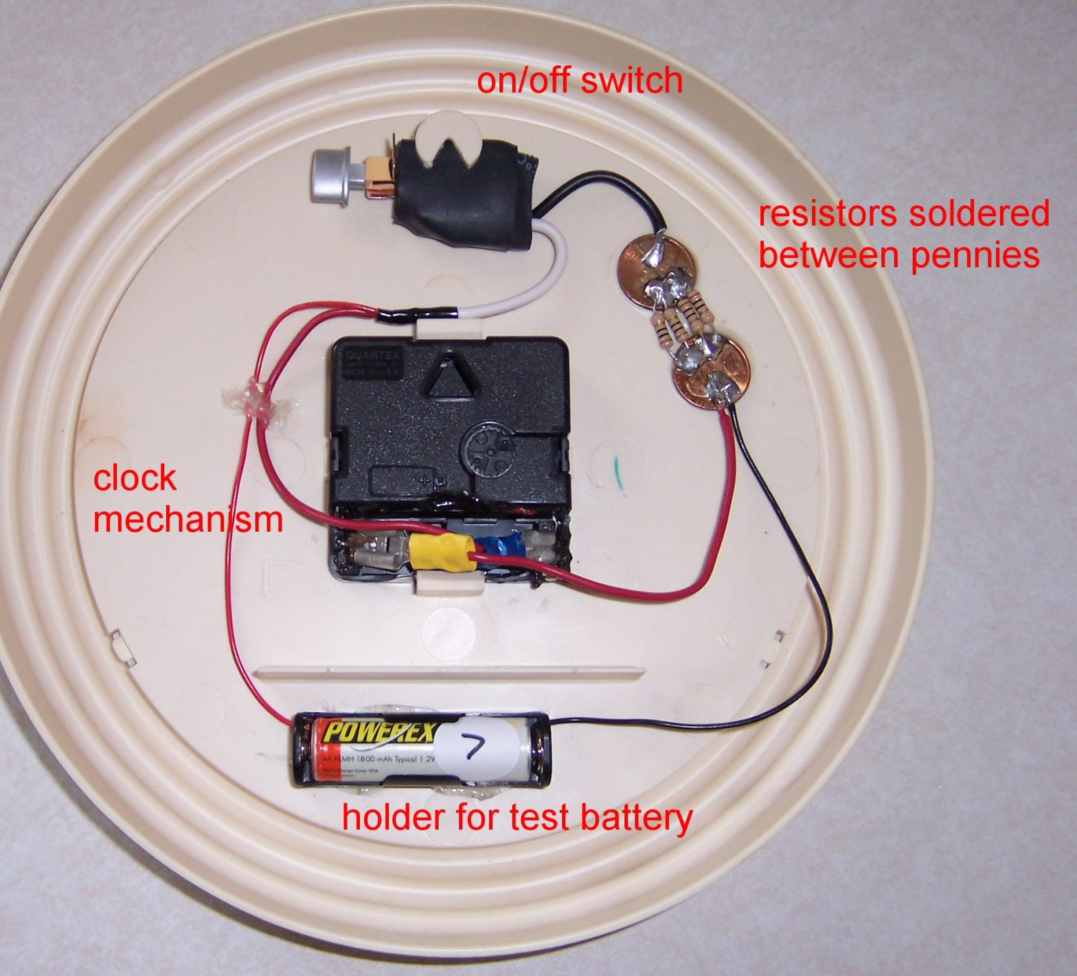
I found plans for a very clever and cheap tester on Nick Hill’s website. Here’s my version of his device, using a larger clock rather than a small watch, because that’s what I had laying around. The wall clock actually worked pretty well, since it provides a mounting surface, is easier to solder, and is easier to wind. I’m not an electronics wizard (as evidenced by my hamfisted attempts at soldering this project) but it was very cheap and easy to make.

Here are the parts needed:
- An quartz analog clock, the kind that takes one AA battery
- AA battery holder (unless you’re better at soldering than me)
- Four 10-Ohm resistors (a single resistor in the 2.5-Ohm range is OK too if you can find one)
- Two pennies
- Solder and wire
- (optional)An on-off switch

Basically, the idea is that the battery is discharged by the resistor while running the clock. At a certain point, the battery’s voltage will drop below that required to run the clock and the hands will stop moving. To test a battery, set the clock on noon, plug in a battery, and let it run. When the clock stops, it shows how long the device ran.
My version discharges the batteries at around 480 milliamps, which is in the same ballpark as a digital camera. My 2000 mAh batteries have typically lasted around 4 hours, so that adds up. I used four 10-Ohm resistors in parallel (which is the same as a single 2.5-Ohm resistor) since I couldn’t find anything smaller than 10-Ohm. Even if this method isn’t incredibly accurate, it still gives you an idea of which batteries are your best.
Construction is simple. First, solder your resistor(s) between two pennies. The pennies work as a heat sink, since you’re basically just dissipating the battery’s energy as heat. Now, wire up the battery holder, clock and resistor as shown in the picture. Note that the clock and resistor are in parallel, not series. You can see Nick’s site for the simple schematic. Finally, use hot glue or something to stick the pieces to the back side of the clock.
I added a switch (salvaged from a broken Apex DVD player) to shut off the resistor. That way I can run the clock alone to set the second hand to 12 o’clock. Of course, over the span of 4 hours, a few seconds doesn’t really matter, so that feature is certainly optional. One benefit, though, is that I can shut off the resistor and it’ll still work as a clock. When I’m done, I can return it back to the wall in the garage and not worry about finding a place to store it!
That’s all there is to it! Thanks to Nick for sharing his clever idea!
can i get an article on the diagram of the mechanism of internal parts of a watch?if yes,plz send it.
Hi Korey,
I have just built a tester similar to yours but have added a series diode to stop the cell from completely discharging. My one uses a watch as the timer the same as Nick’s.
Neil
I use the same design, but prefer to set the clock to midnight instead of noon. I feel this is a significant improvement.
I use the same design, but prefer to set the clock to midnight instead of noon. I feel this is a significant improvement!
Good point, Rob. I’m going to have to retest all my batteries now…
what a great, simple, design! Kudos from the KISS University………..