

Published: 1/31/2010
Trying to solve the problem of my shop vac filter quickly clogging with sawdust, I came across SimonSKL’s blog post on Lumberjocks.com. In his post he describes a do-it-yourself cyclone dust collector. This device uses a cyclone effect (much like a Dyson vacuum) to cause the dust and chips to drop out of the air stream before reaching the vacuum itself.
I take no credit for the design, but here’s my version of his creation:
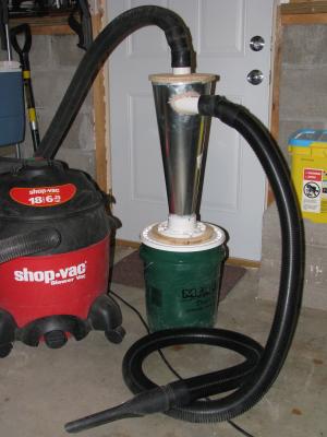
This dust separator took me about 3-4 hours to build, and uses about $25 in materials.
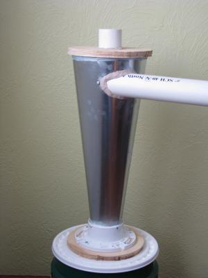
In short, this device consists of a metal cone, inlet and outlet pipes, and a bucket at the bottom to collect the material. Air and dust enter the pipe mounted on the side and spin inside the cone. As the air slows, the dust and wood chips fall into the bucket, and the air continues to the vacuum through the outlet pipe mounted at the top. Simon’s post covers the construction pretty well, so I’ll just briefly describe the specifics of my build.
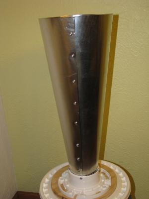
I started with an 8″ by 24″ piece of duct work and formed it into a segment of a cone, about 8 inches wide at the top, and about three inches wide at the bottom. I held it together with a bunch of sheet metal screws.
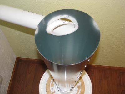
The top of the cone is capped with a 9″ circle of 3/4″ plywood. Using a router and a circle jig, I routed a 1/4″ groove 8 inches in diameter in the bottom of the cap. This groove is to fit the top of the cone in. I drilled a hole in the center just big enough to fit a piece of 2″ PVC pipe through.
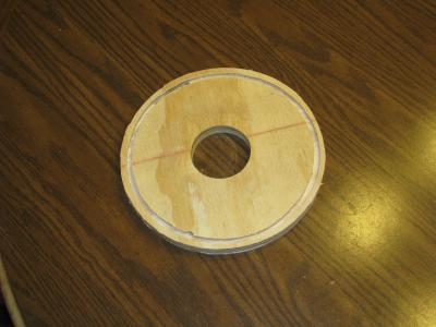
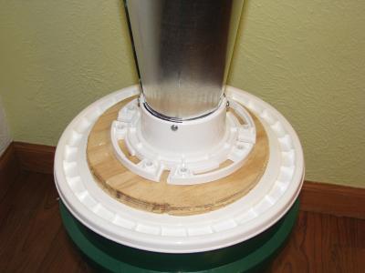
The bottom of the cone is held by a PVC flange that I found near the floor drains at Menards. I used pan head screws to attach the cone to the flange. I mounted that flange to another 9″ plywood circle with a hole cut in it, then I mounted the plywood circle to the lid of the bucket, also with a hole in it. I used screws to hold it together and silicone caulk to make the joints basically airtight.
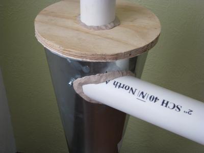
The tricky part is mounting the inlet pipe on the side of the cone. Despite the possibilities of drawing a template and figuring everything out, I mostly just eyeballed this part. The pipe is cut on an angle and mounted about 1-1/2″ inches from the top of the cone. The idea is for the air to enter the cone and ride along the wall, so try to get it entering as close to tangentially as possible.
Thanks to Billy Mays, I found some Might Putty (epoxy putty) to seal this inlet tube to the metal cone. It worked well because I had a pretty big gap to fill, since I just guessed at the size of the hole to cut. Likewise, I mounted the outlet pipe in the lid. The outlet pipe extends just below the bottom of the inlet pipe.
Finally, I sealed the top cap onto the cone then caulked the remaining seams to prevent air leaks.
For a standard 2-1/2″ shop vac hose, I found some 2″ rubber “no-hub couplings” that fit pretty well on both the 2″ PVC and to the shop vac hose. They come with hose clamps, so I’ll probably mount them tightly, but even without them, the fit is pretty good.
In my testing, my first trial was very disappointing. Only about half of the material was trapped in the bucket, the rest proceeding to the shop vac itself. Thankfully, the fix was simple: hook it up properly! The hose to the shop vac mounts in the top, and the hose to your tool or wand hooks to the side. After I set it up properly, nearly all of the wood chips and sawdust stayed in the bucket. The sound of the chips hitting the metal cone are music to my ears, letting me know I’ll save on shop vac filters and bags!
So the top mount had to go down further than the suction tube, like 4 inches or so. This way it don’t go right into the shop vac. Excellent setup, I love it, you got me building one. I appreciate any feedback, before I throw away to much money.
Thanks Vinman
Yep, that’s right, probably about 4 inches- just below the bottom of the inlet tube. I don’t really know if that’s the optimal setup, but it makes sense (not providing a straight path to the vacuum).
The only update I have, having used this setup quite a bit, is that the mighty putty is cracking and not holding up very well. I’ve since braced the inlet tube using a piece of wood run from the top of the cone to the bottom. I resealed that joint with regular silicone caulk.
Best of luck!
Yes, intake for the outlet [ie, line to vac] should be anywhere from 1/4 to 1/3 of the way from the top of the cyclone, and shouldn’t be more than 1/3 the dia. of the cyclone at it’s mouth [eg, a 2″ dia line to vac inside the cyclone should not extend below a pt. where the ID of the cone is <6".] Kudos on making it clear that the intake line at the top of the cyclone must be tangential! Most folks don't understand the physics well enough to get that critical detail right. 🙂